LED wall EDID settings tell a connected video source which display capabilities are being advertised. They do not, by themselves, map cabinets, repair a cable or make a source output the timing you intended. Before changing the wall layout, compare three records: the source’s actual output, the processor’s detected input and the configured LED canvas.
A useful commissioning sequence is to establish a supported input first, verify that the processor receives it, and only then review scaling, cropping and fixture mapping. Save the working configuration before making changes. The examples here are illustrative planning cases, not tests of a particular installed system. Exact menus, supported timings and restart behavior depend on the processor, firmware, graphics driver and any equipment between the source and processor.
What EDID identifies
Microsoft describes EDID as display identification and capability metadata supplied to the host. In a processor-based LED installation, the video source is connected to an input device with its own advertised capabilities; the source does not discover the physical cabinet arrangement merely by reading that metadata.
A processor may expose standard or configurable capabilities. As one documented example, Brompton’s project-management help says enabling HDR changes the EDID advertised by specified processors. This illustrates advertisement of an input capability, not a universal instruction to enable HDR. Follow the manual for the actual model and configuration.
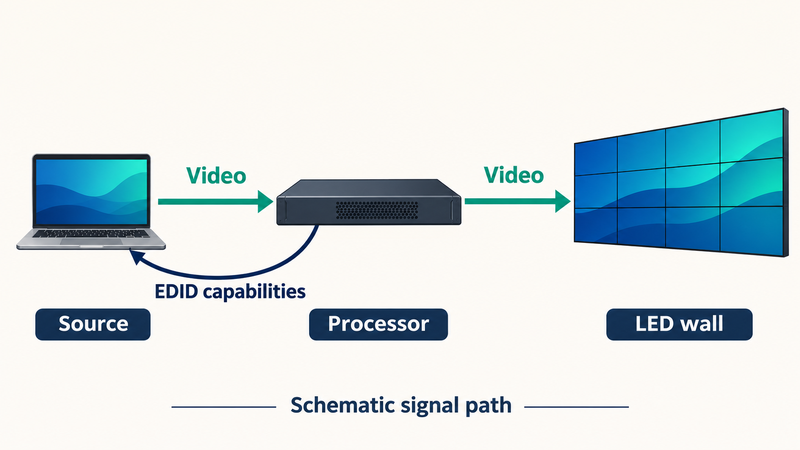
Record input timing and canvas separately
| Record | Where to confirm it | What it does not establish |
|---|---|---|
| Advertised EDID / preferred mode | Processor input settings and what the source reads | The source is currently transmitting that mode. |
| Actual source output | Graphics output or playback-device status | The processor has locked to it. |
| Detected input width, height and frame rate | Processor input-status display | The content is correctly placed on the LED canvas. |
| Canvas, crop/scale and fixture mapping | Processor project and wall test pattern | Every possible input timing will work. |
Keep the complete timing rather than a label such as “HD” or “4K.” Width and height without frame rate are an incomplete record. Brompton’s version 2.3.2 release notes, for example, explain that supported pixel capacity changes with frame rate and interface limits. That is a model-and-version example, not a current capacity promise for every processor.
How to review the settings in order
- Save the starting state. Export the processor project using its supported method. Record model, firmware, input port and the source output before the change. Confirm how to restore that configuration.
- Check the whole connection path. Identify adapters, extenders, splitters or switchers between the source and processor. Do not assume a direct-connection result describes the installed chain.
- Choose a documented supported input. Review the current manual’s width, height, frame-rate and format constraints. Do not copy a custom EDID file from an unrelated device just because its resolution looks suitable.
- Confirm actual output and lock. After applying the advertised mode, recheck what the source sends and what the processor detects. Use the manufacturer’s documented refresh or reconnect procedure if needed, within a planned test window.
- Review the canvas afterward. Display a known test pattern and inspect scale, crop, image position and cabinet order. Change one variable at a time and retain a working rollback point.
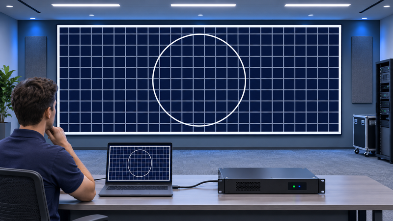
Compare two illustrative canvas approaches
Suppose the physical wall has 1536 × 768 pixels. One possible plan is a matching custom input, if the source, processor and connection path support it. Another is a supported standard input such as 1920 × 1080, with content positioned, cropped or scaled into the intended canvas region. These are different design choices; neither follows automatically from the cabinet count.
A 16:9 image does not become a 2:1 composition merely because an EDID is changed. Decide whether to preserve the full picture with unused area, crop part of it or create content for the wider aspect ratio. If exact pixel correspondence is required, document the source raster, content coordinates and processor mapping explicitly.
Brompton’s canvas documentation illustrates why a generic rule is insufficient: supported canvases and custom-resolution conditions differ by processor, with exceptions requiring input and canvas sizes to match. It also calls for testing custom settings before production use. The dimensions above are an arithmetic example, not a compatibility statement about a named product.
Match the symptom to the next check
If the desired mode is absent at the source, inspect the advertised capabilities and the intervening devices first. If the mode is selected but the processor shows no valid input, compare the actual timing and supported input path; an EDID advertisement alone is not proof of a working transport.
If the processor has a stable input but the picture is stretched, misplaced or divided across cabinets incorrectly, review scaling, coordinates and mapping instead of repeatedly changing EDID. If a particular protected source fails while an ordinary test pattern works, treat content protection as a separate compatibility question. Our LED wall HDCP guide explains that distinction without bypass instructions.
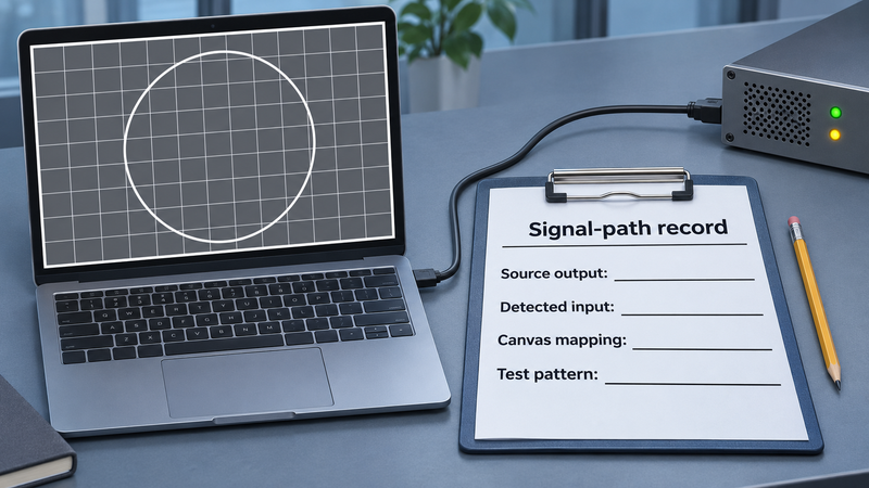
Keep a reproducible handover record
Save the approved project, source output settings, detected-input status and a photograph of the complete test pattern. Record the tested connection chain and the content used. A successful test with one laptop and cable does not verify a later switcher, another source or a different frame rate.
For timing across multiple devices, continue with genlock versus low latency. EDID review should finish with a repeatable, documented signal path and correctly placed content, rather than a resolution number that merely appears in a menu.
Sources checked November 13, 2026: Microsoft’s EDID description and the identified Brompton help pages and versioned release notes. Examples, diagrams and workflow suggestions are editorial explanations; no live hardware test, quoted product capacity or supplier certification is claimed.