Genlock and low latency address two different problems on an LED wall. Genlock aligns frame timing to a reference. Low latency reduces the delay through a processing path. A camera-facing wall may need stable timing with the camera system. A live camera feed shown to the audience may need a shorter delay. Some setups need both outcomes, which makes the processor’s mode restrictions important.
Compare genlock and delay in three signal chains
| Situation | First question | What to observe |
|---|---|---|
| Camera films an LED backdrop | Are the relevant devices locked to a common reference? | Stability in the recorded image at the intended camera settings |
| Audience sees a live camera feed and the presenter together | How long does the displayed action trail the source? | Measured end-to-end delay through the show’s actual path |
| Two processors feed different wall sections | Are timing and processing delays matched across them? | A moving test edge crossing the join between sections |
A wall can be stable against a timing reference and still show an image several frames late. A fast path can still be unsuitable for a camera shot if its timing is unstable or incompatible with the rest of the chain.
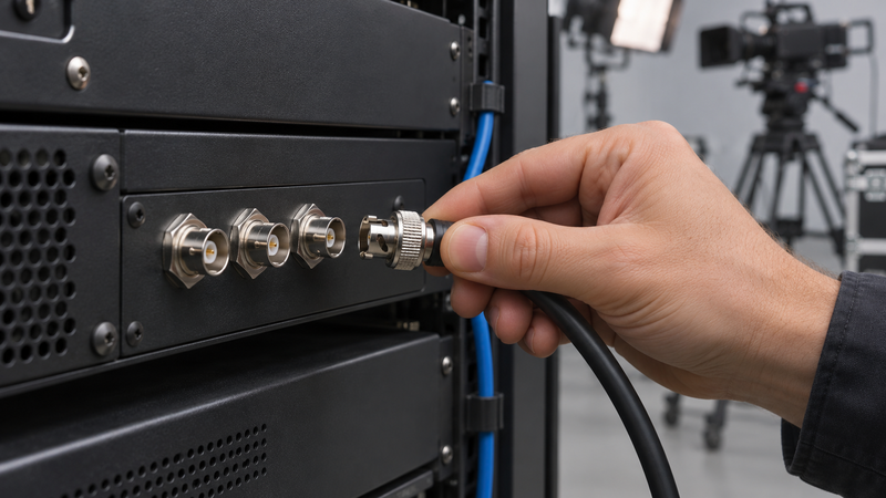
Read the mode restriction in the exact manual
The NovaStar MX40 Pro user manual, V1.5.0 says the sync source cannot be set to Genlock when the controller’s low latency function is enabled. The manual also gives different controller latency figures by working mode. Neither figure measures a complete chain that includes a camera, switcher, conversion, and the wall.
For a different example, Brompton’s guidance on combining Tessera processors calls for both a shared timing relationship and matched delays across wall sections. Shortening only one processor path could create a mismatch at the join. Check the exact models, firmware and modes before assuming either vendor example applies to your system.
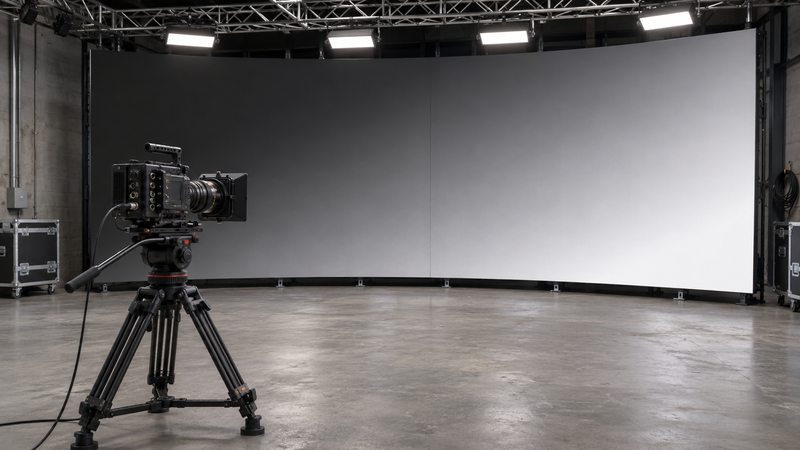
Run one timing check and one delay check
For the timing check, use the show’s intended source rate, camera shutter settings and reference signal. Confirm lock on the relevant devices and record a test pattern in motion. If the wall is split, carry the pattern over the seam. Inspect the recording alongside the device status. If banding is the symptom, check the camera and display settings as well as reference lock. The refresh-rate setup checklist covers a separate part of that diagnosis.
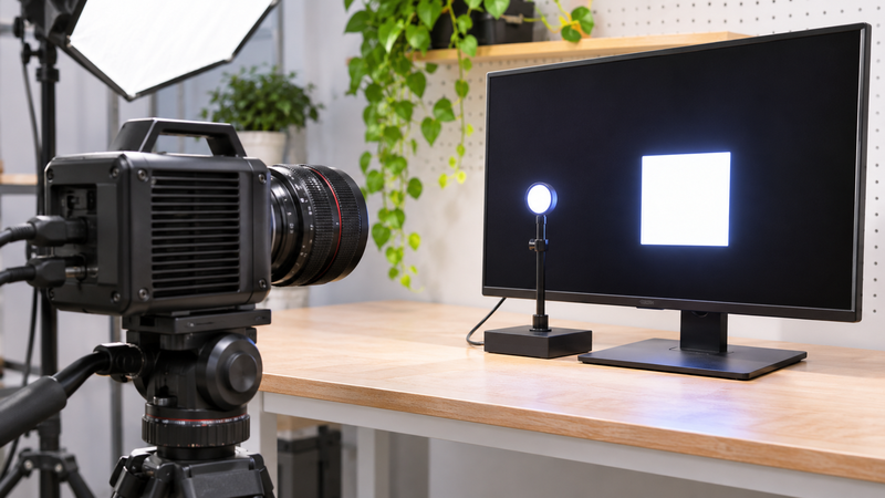
For the delay check, put an observable visual event at the input and capture that event and the displayed result in the same high-frame-rate recording where practical. Repeat it and document the measurement method. At a 60 Hz source rate, one source frame interval is about 16.7 ms. A vendor’s one-frame controller figure is not a measurement of the total delay. Use the same test method for each candidate mode.
Write the acceptance criteria before changing the mode
For the camera-facing wall, specify what a stable recorded image must look like under the actual shoot settings. For live audience display, agree on an end-to-end delay target for the event. Record any compromise if a controller mode cannot meet both at once, and repeat the checks after a wiring, input or mode change. The LED video processor setup guide is a starting point for documenting that signal path.
Frequently Asked Questions
Can genlock and low latency run at the same time on an LED wall?
Check the exact controller and working mode. The NovaStar MX40 Pro V1.5.0 manual says its sync source cannot be set to Genlock when low latency is enabled. Other processors can behave differently, so verify both timing and delay on the installed signal chain.