Quick answer: The moire effect in photography can appear when a camera samples a fine repeating pattern, including an LED wall’s pixel grid. Test the camera’s position, framing and background focus before blaming one display specification. If you see moving dark bands instead, investigate the camera shutter and LED timing as well. Spatial moire and timing artifacts can coexist, but they are not the same diagnosis.
For an LED-wall project, a screen that looks clean to an audience may still produce artifacts in the camera image. Acceptance therefore needs the intended camera, lens, shot and recorded file. A supplier’s generic phone clip or one impressive refresh-rate number cannot establish that your production setup will work.
The procedure below is a controlled test plan for an AV or camera team. It does not prescribe a universal pixel pitch, shutter speed or camera distance. Keep the required framing and subject sharpness in view while evaluating each change.
Identify the artifact before changing settings
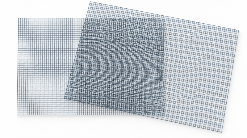
Adobe’s aliasing explanation describes how fine repeating textures can produce false waves or colors in a captured image. An LED grid is one such repeated structure. The visible interference pattern can be larger than the individual pixels that produced it.
| What you observe | First test | What it does not prove |
|---|---|---|
| Wavy or colored pattern that changes with framing | Change camera position or focal length slightly, then compare recordings. | That the wall’s refresh rate is defective. |
| Dark bands or brightness variation across recorded frames | Review shutter, frame rate, synchronization and the LED operating mode. | That a lens or focus change alone will resolve it. |
| Pattern appears only in a resized preview or export | Compare the original recording and final delivery at the intended viewing scale. | That the original capture contains exactly the same artifact. |
This table is a starting point, not a diagnostic instrument. Keep a short original clip for each observation. Looking at a paused, scaled camera preview alone can hide one issue or introduce another apparent pattern.
How to test geometry and focus one variable at a time
Start with a representative shot and save it as the baseline. Record the lens, focal length, aperture, focus position, camera-to-subject distance and subject-to-wall separation. Also save the frame rate, shutter setting, recording format and wall configuration so the baseline can be restored.
- Change the viewing geometry. Try a small change in camera position or framing, within the production’s permitted shot. Record the result rather than assuming closer or farther always wins.
- Separate framing from perspective. A focal-length change checks composition and required subject coverage; a camera-position change checks perspective and spatial relationships. Record which one changed.
- Test background focus deliberately. Where the wall is a scenic background, assess whether more subject-to-wall separation and a suitable depth of field keep the subject sharp while reducing visible grid detail.
- Restore the baseline between tests. Change one variable at a time so a better result has an identifiable cause.
Brompton’s on-camera guidance discusses separating the screen from foreground elements and choosing the lens and depth of field accordingly. That is useful for a background scene. It may be unacceptable for a wall displaying text, diagrams or a product image that must remain sharp; test against the actual content requirement.

Separate moire from LED and shutter timing
Do not treat a refresh-rate upgrade as an automatic cure for a spatial pattern. Camera sampling of a grid and the timing relationship between the camera and the LED system are different parts of the problem. A useful test log keeps both sets of conditions.
Brompton’s ShutterSync documentation explains matching LED refresh timing to a camera shutter and lists specific compatible hardware. It demonstrates why the actual processing chain matters; it does not mean every controller provides the same feature or that LEDP3 equipment supports it without confirmation.
If the symptom points to timing, use the relevant camera and processor manuals with the technical team. Retest the spatial pattern after any timing adjustment instead of marking the whole issue resolved from one changed setting.
Moire effect photography checklist for an LED-wall test
Ask for a test that resembles the planned production. Include the nearest required framing, representative background detail, a foreground subject where relevant and the wall brightness intended for the shoot. If multiple cameras or lenses will be used, include each required combination rather than extrapolating from the easiest one.
- Panel model, pixel pitch and relevant operating configuration.
- Processor, firmware and receiver configuration, identified by the supplier.
- Camera body, sensor/recording mode, lens and focal length.
- Aperture, focus position, shutter and frame rate.
- Camera, subject and wall distances, plus the tested framing.
- Original recording, delivery export and a clear note about what changed.
Brompton’s Getting Started with LED on Camera connects pitch choice to the planned shots and lenses. Use that as a reason to request a representative test, not as a basis for promising that one pitch is always camera-safe. A passing setup remains conditional on the configuration actually tested.
Check the recorded file and delivery export
Review the original recording on an appropriate monitor, then check the actual delivery version. Adobe notes that resizing can change the appearance of aliasing. Keep track of playback scale and export settings so a pattern introduced downstream is not confused with the initial capture.
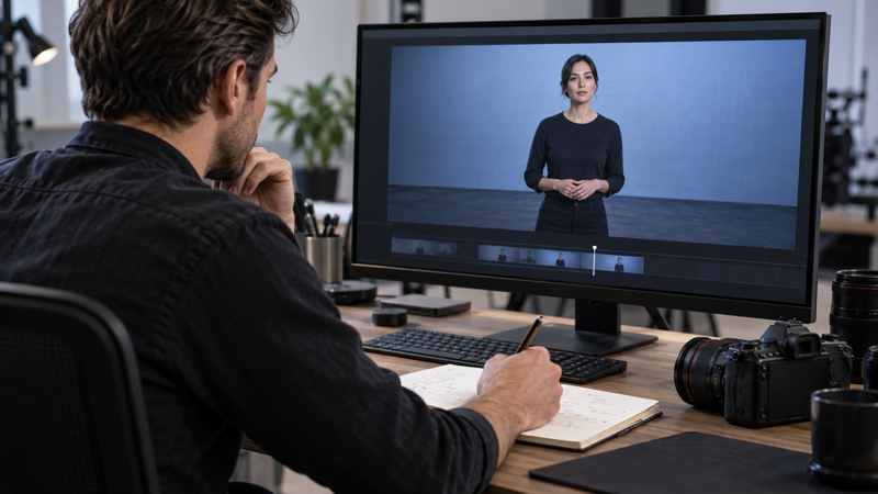
Editing may reduce a residual pattern, but blur and other corrections can also sacrifice useful detail. Before relying on post-production, check faces, hair, text and the intended background at delivery size. Save the original alongside the corrected version. For a procurement decision, the deliverable is a reproducible test record, not a claim that the wall will be artifact-free in every future shot.
Questions from a camera test
Does a higher refresh rate eliminate moire?
Not by itself. Spatial patterns depend on the camera’s sampling of the scene; temporal bands also involve camera and LED timing. Identify and test each symptom separately.
Should I always blur the LED wall?
No. A softly focused scenic background may be acceptable, while text or product detail may need to stay sharp. Preserve the shot’s content requirements.
Does a finer pixel pitch guarantee a clean shot?
No. Pitch is one factor alongside camera, lens, framing, focus and configuration. Verify the intended setup with a recorded test.
Can I fix the problem entirely in editing?
Sometimes correction helps, but it can reduce detail and may not suit every frame or delivery. Test capture changes first and review the final export before accepting the result.
Technical sources and limits
Sources checked October 28, 2026: Adobe’s aliasing guide; Brompton’s on-camera setup guidance, ShutterSync feature documentation and LED-on-camera paper. The test sequence is editorial guidance. No original bench test, camera compatibility certification or universal optimum is claimed.