“SMD vs COB” is usually asked as if it were a two-column feature contest. That framing hides the decision that affects a buyer most: whether a complete display system works in the real room and remains supportable after handover. Packaging influences the result, but so do the LED chip, driver IC, scan design, calibration, cabinet, surface treatment, thermal path, controller, processing settings, and installation quality.
The right comparison therefore starts with the project. Record the closest viewer, screen dimensions, target resolution, ambient light, camera use, touching or impact risk, operating hours, service access, local support, and spare-parts plan. Then ask suppliers to quote SMD and COB options against that same requirement. A premium-sounding label is not a substitute for a matched sample test or a written service method.
What SMD and COB actually describe
SMD, or surface-mounted device, typically mounts discrete LED packages to the module PCB. In full-color displays, a common package integrates red, green, and blue chips that can be driven separately; other package arrangements also exist, so the acronym does not define every internal design. The packages remain visible as discrete points on the surface. This is a mature route used across many indoor, outdoor, fixed, and rental products, but the performance range is wide.
COB, or chip-on-board, mounts bare LED chips directly to a substrate and protects a larger area with an integrated encapsulated surface. ViewSonic’s support explanation uses this direct-to-substrate structure to distinguish COB from SMD. “COB” still does not identify every design detail: flip-chip route, encapsulation, surface finish, driver scheme, calibration, and module construction can differ by product.
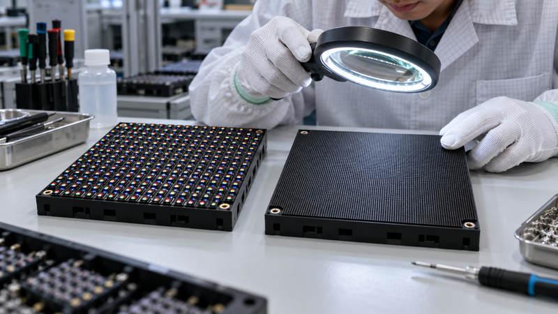
Official product portfolios also show why the label is only one layer. LG’s commercial DVLED matrix includes both COB and single-SMD systems across overlapping resolutions and pitch classes. Planar likewise groups commercial LED video walls across a broad pixel-pitch range and multiple technology families. The practical question is not “Which acronym wins?” but “Which complete model meets this project’s viewing, protection, service, and budget requirements?”
Choose by project conditions
| Project condition | Why SMD may stay on the shortlist | Why COB may stay on the shortlist | What to verify |
|---|---|---|---|
| Standard indoor pitch and controlled viewing distance | Broad, mature product choice and familiar service workflows. | May still be offered, but the added surface protection must justify the system cost. | Actual pitch, minimum viewing distance, brightness range, low-gray image, and quote scope. |
| Fine-pitch boardroom or control room | A well-engineered SMD wall can remain viable where support and spares are strong. | Smooth encapsulated surfaces and very fine-pitch options can be useful for close viewing. | Pixel structure at the closest seat, reflections, seam visibility, heat, fan noise, and front service. |
| Public area with touch or impact risk | Use only if the product’s protection and replacement plan fit the risk. | Integrated surface protection may better resist incidental contact. | Surface hardness claim, cleaning method, edge protection, damaged-module procedure, and warranty exclusions. |
| Rental or frequent reconfiguration | Established module and cabinet replacement workflows may be more useful than a sealed surface. | Consider only when the supplier proves handling, repair, and spare turnaround fit the rental operation. | Corner protection, quick locks, module swap time, flight cases, field tools, and technician training. |
| Strict lifecycle budget | Lower purchase price can help, but only if failure exposure and labor are included. | Higher initial cost may be defensible where reduced surface damage or different power behavior is proven. | Five-year energy model, spare stock, labor, shipping, calibration, downtime, and warranty response. |
Compare image behavior on a sample wall
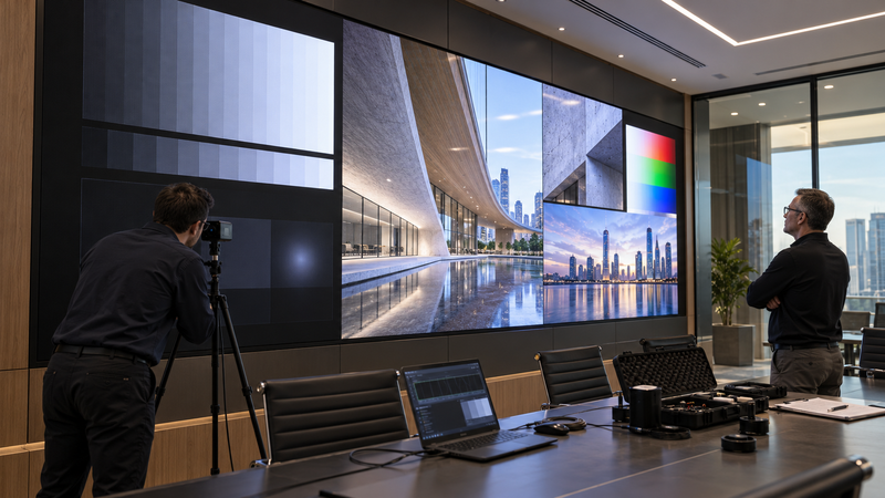
Do not accept a showroom demo that uses different pitches, different screen sizes, or different brightness settings. Ask for matched samples and view them from the closest real seat, the side seats, and the camera position. Run dark gray ramps, skin tones, fine text, moving gradients, saturated colors, and the content your team will actually display.
Low gray and uniformity
At low brightness, look for color tint, blotching, uneven rows or columns, crushed shadow detail, and differences between modules. Calibration and driver behavior can dominate these observations. A packaging claim alone cannot prove that one sample has better low-gray performance.
Black level, reflection, and viewing angle
Turn on the room lighting and observe the surface from front and off axis. Compare reflected ceiling fixtures, windows, and camera lights. A dark matte surface may improve perceived contrast, but measure and view the complete wall because masks, coatings, surface texture, and ambient light all contribute.
Camera behavior
If the wall appears on camera, test the planned frame rates, shutter speeds, scan rates, and angles. Look for scan lines, flicker, moire, color shift, and brightness headroom. The package type does not replace a camera test. The existing guide to conference-room LED screen selection can help you define viewing distance, content, and room constraints before the demo.
Compare serviceability and lifecycle cost
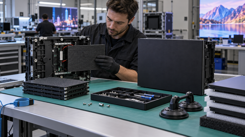
SMD is often described as “easy to repair” and COB as “hard to repair.” That is too broad. Some systems support fast front module exchange; others require depot repair or calibrated replacement panels. A technician may be able to replace an SMD component at a workbench, but that does not mean pixel-level field repair is economical or visually acceptable. A COB product may use module-level replacement that is straightforward on site even though chip-level work returns to a specialist facility.
Ask each supplier to demonstrate the exact service process. Time a front-module removal. Confirm whether a replaced module needs stored calibration coefficients, how batch color differences are handled, which tools are included, and whether local technicians are authorized. Record the minimum spare quantity, storage conditions, shelf-life guidance, and turnaround time for factory repair.
For lifecycle cost, separate rated component life from installed-wall life. Operating temperature, drive level, brightness, content, dust, humidity, power quality, calibration policy, and maintenance all affect the result. The article on reading LED video wall lifetime ratings explains why an hour rating is not a replacement forecast.
Cleaning also needs product-specific instructions. A protected surface may tolerate a different workflow from exposed packages, but no buyer should assume that any liquid, cloth, or pressure is safe. Obtain the manufacturer’s approved method and align it with the site’s maintenance team. Use the LED screen cleaning checklist to plan isolation, tools, and inspection.
Request a matched quotation
A usable quotation must keep the comparison boundary stable. Give both suppliers—or both product teams—the same wall dimensions, resolution target, pixel pitch range, viewing distance, brightness target, content, duty cycle, electrical supply, installation access, controller inputs, redundancy needs, warranty expectations, destination, and commissioning scope.
| Quote item | Request in writing | Why it matters |
|---|---|---|
| Display architecture | Package route, chip orientation, module and cabinet dimensions, pitch, resolution, scan ratio, driver IC, and surface treatment. | Prevents an acronym-only comparison. |
| Optical conditions | Typical and maximum brightness, contrast test method, color temperature range, grayscale, refresh, and viewing angle method. | Published values are meaningful only with test conditions. |
| Power and thermal data | Maximum and typical power at a stated brightness and content pattern, heat load, ventilation, and operating temperature. | Supports electrical, HVAC, and lifecycle planning. |
| Service plan | Access direction, swap procedure, repair level, calibration process, included tools, spare quantities, and response times. | Turns “easy maintenance” into an auditable workflow. |
| Commercial boundary | Equipment, structure, processor, cabling, installation, commissioning, training, freight, duties, warranty labor, and exclusions. | Prevents a low headline price from hiding system costs. |
Do not compare a premium fine-pitch COB system with a larger-pitch entry SMD wall and attribute every difference to packaging. Match the variables that affect the user experience. If two offers cannot be normalized, mark the comparison as incomplete rather than forcing a winner.
Run a buyer-side acceptance test
- Confirm identity. Match model, pitch, package route, module batch, controller, firmware, and quoted accessories.
- Inspect the surface. Check scratches, chipped edges, contamination, dead or unstable pixels, seams, flatness, and module-to-module color.
- Run image patterns. Use white, primary colors, low-gray ramps, gradients, fine text, motion, and real content at stated settings.
- Change the room conditions. Test normal lighting, dark presentation mode, side viewing, closest seat, and planned camera positions.
- Test power states. Verify cold start, restart, signal loss, input switching, backup behavior, and recovery after an interruption.
- Demonstrate service safely. Have supplier-authorized personnel remove and replace a module only after power is shut down and isolated under the manufacturer’s procedure for that exact model; then reload calibration if needed and confirm the spare produces an acceptable match.
- Record evidence. Save settings, photos, test content, serials, measured conditions, defects, corrections, and signed acceptance boundaries.
A sample-room pass is not final site acceptance. The installed wall adds structure, power distribution, signal transport, ambient light, ventilation, and workmanship. Repeat the agreed tests after installation and before final payment.
Questions about SMD and COB
Is COB always better than SMD for an LED wall?
No. COB can be attractive for fine pitch, close viewing, and protected surfaces. SMD can be the better operational fit where product choice, field support, module replacement, and initial cost matter more. Compare actual systems, not only packaging labels.
Does COB automatically use less power?
No universal conclusion follows from “COB” alone. Compare equal screen area, resolution, brightness, content, settings, and test method. Driver design, scan ratio, common-anode or common-cathode architecture, efficiency, and thermal conditions also affect power.
Which is easier to repair, SMD or COB?
It depends on the product and service network. SMD may support component or module repair through established workflows. COB often uses protected modules that are replaced on site and repaired at a specialist facility. Ask for a live service demonstration and written spare policy.
What should be matched in an SMD versus COB demo?
Match pixel pitch, screen size, resolution, brightness, color settings, content, room lighting, viewing positions, controller path, and camera settings. Also compare module swap time, calibration, spare cost, warranty, and repair turnaround.
Sources and limits
- ViewSonic Support: What is COB technology on a DVLED display?
- ams OSRAM: multi-chip RGB LED in an SMT package
- LG Business: Ultimate Business Display product matrix
- Planar: commercial LED video wall portfolio
Boundary: This guide explains a procurement method, not a universal product ranking. Vendor specifications and portfolio examples are model-specific. Confirm the exact data sheet, sample, test conditions, service agreement, electrical design, structure, and local installation requirements for the proposed system.